As part of your design process, you'll need to start with a block diagram, circuit schematic, and eventually a PCB layout
Home
› Understanding Electrical Diagrams : Understanding Relays Wiring Diagrams Swe Check : As with any good troubleshooting tool, one must be familiar with its basic features to make the most of the diagram in the field.
Understanding Electrical Diagrams : Understanding Relays Wiring Diagrams Swe Check : As with any good troubleshooting tool, one must be familiar with its basic features to make the most of the diagram in the field.
Understanding Electrical Diagrams : Understanding Relays Wiring Diagrams Swe Check : As with any good troubleshooting tool, one must be familiar with its basic features to make the most of the diagram in the field.. A wiring diagram is a simple visual representation of the physical connections and physical layout of an electrical system or circuit. Knowing the meanings of basic electrical symbols in your electrical drawing will help you quickly understand and troubleshooting the circuit. It will typically show a set of symbols and a brief description. Here are some of the standard and basic symbols for various components for electrical schematics. A well documented schematic outlines the functionality of an electric circuit and provides the basis for assembly and troubleshooting of a system.
Describe and identify the diagram component u. We'll go over all of the fundamental schematic symbols: This is sometimes a long wiring run on a boat. Schematics are our map to designing, building, and troubleshooting circuits. This means that you connect them with a wire when the black lines cross in a diagram there are ways of telling whether or not the wires should be connected to each other as shown below.
Wiring Diagrams Explained How To Read Wiring Diagrams Upmation from upmation.com It will typically show a set of symbols and a brief description. A schematic diagram is a drawing that shows physical components in their proper positions within a system, but not necessarily in their actual physical location. Learning how to read and understand schematics will be easy for beginners with recognizing basic schematic symbols. A single line can show all or part of a system. A lamp is usually represented as a circle with a cross inside it. Switches are symbolized by an opening or break in the line. With a basic grasp on understanding electrical diagrams, technicians and engineers are able to develop a logical pattern of troubleshooting that can aid in the successful analysis of systems. A well documented schematic outlines the functionality of an electric circuit and provides the basis for assembly and troubleshooting of a system.
This is what we draw using autocad electrical.
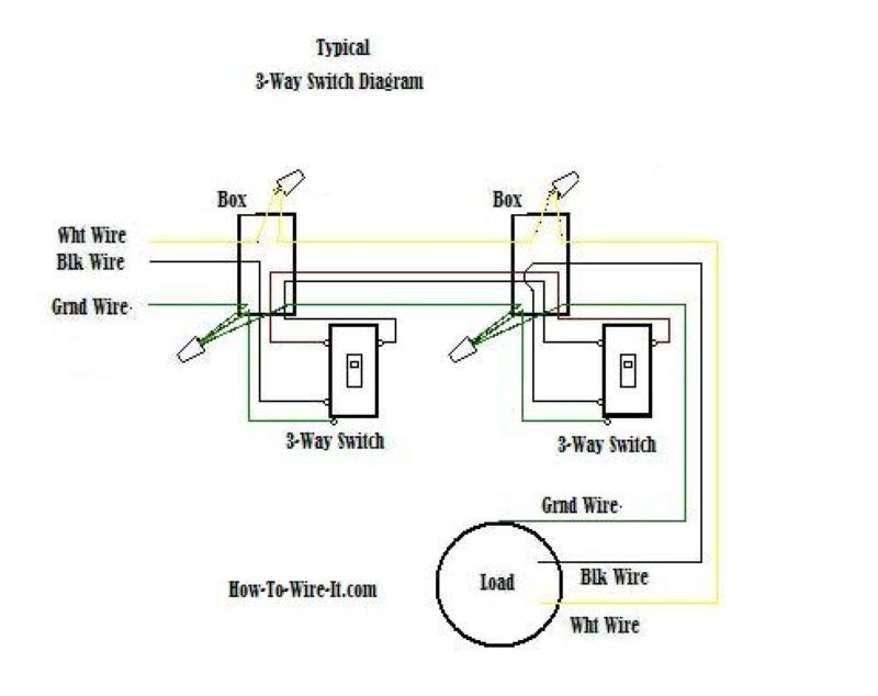
It shows how the electrical wires are interconnected and can also show where fixtures and components may be connected to the system. A lamp is usually represented as a circle with a cross inside it. A well documented schematic outlines the functionality of an electric circuit and provides the basis for assembly and troubleshooting of a system. Physically parts are connected by wires, in the diagrams you will see black lines going from one part to the next. When and how to use a wiring diagram That idea is then defined, with words and diagrams, in a specification. Wire diagrams use wire color codes to identify the color of wire being used to connect different electrical components within the circuit. Understanding electrical diagrams rv 7.11.19 5 quiz 3: The power supply is shown at the top and the earth at the bottom to facilitate understanding of the current flow. The symbols and lines within an electrical drawing. Understanding toyota wiring diagrams worksheet #1 1. This tutorial should turn you into a fully literate schematic reader! Electrical schematics are the maps for designing, building, and troubleshooting circuits.
Some wire colors are specific to the wire's use such as black, white, red, and green, while others are used for component connection and change function from one circuit to another. The symbols and lines within an electrical drawing. Electrical diagrams are the most commonly used drawings. Which of the above is the symbol for field A wiring diagram is a simple visual representation of the physical connections and physical layout of an electrical system or circuit.
Wiring Diagram A Comprehensive Guide Edrawmax Online from images.edrawmax.com Schematics are our map to designing, building, and troubleshooting circuits. To begin understanding how to read and understand electrical circuit diagrams, take our basic circuit and draw it out as it would physically be wired. When the current passes through the lamp, it will produce light. Circuit schematics are the bridge between conceptual electrical design and physical realization of a printed circuit board assembly, or pcba. This class presents a logical approach to troubleshooting electrical power systems. Some wire colors are specific to the wire's use such as black, white, red, and green, while others are used for component connection and change function from one circuit to another. Understanding electrical wiring diagram and termination. We walk through some of the basics and most common symbols associated with reading an air conditioner wiring schematic or diagram.read all the tech tips, tak.
Schematic electrical wiring diagrams are different from other electrical wiring diagrams because they show the flow through the circuit rather than the physical a wiring diagram is the most common form of the electrical wiring diagram.
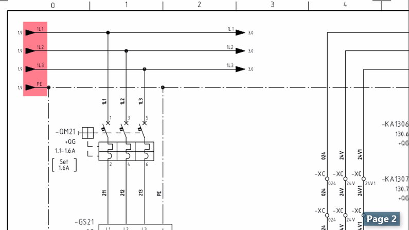
A single line can show all or part of a system. As you examine individual control circuits and the associated components that they operate, the overall diagram becomes easier to understand, as do the The power supply is shown at the top and the earth at the bottom to facilitate understanding of the current flow. Wire diagrams use wire color codes to identify the color of wire being used to connect different electrical components within the circuit. This is what we draw using autocad electrical. Some wire colors are specific to the wire's use such as black, white, red, and green, while others are used for component connection and change function from one circuit to another. Whenever you determine your specific field of electrical engineering, you may see more complex diagrams and symbols. Switches are symbolized by an opening or break in the line. A wiring diagram is a simple visual representation of the physical connections and physical layout of an electrical system or circuit. We show our ac power source on the left with l1 and n coming out of it, our switch to the top, and our light to the left. Anyone can take an idea this far, but the next step requires a fundamental understanding of circuit schematics. A drawing of an electrical or electronic circuit is known as a circuit diagram, but can also be called a schematic diagram, or just schematic. A well documented schematic outlines the functionality of an electric circuit and provides the basis for assembly and troubleshooting of a system.
Learning how to read and understand schematics will be easy for beginners with recognizing basic schematic symbols. A well documented schematic outlines the functionality of an electric circuit and provides the basis for assembly and troubleshooting of a system. This tutorial should turn you into a fully literate schematic reader! Schematics are our map to designing, building, and troubleshooting circuits. When the current passes through the lamp, it will produce light.
Electrical 1 Electrical Diagrams Training Video from www.convergencetraining.com A wiring diagram may include the wirings of a vehicle. Describe and identify the diagram component u. Circuit or schematic diagrams consist of symbols representing physical components and lines representing wires or electrical conductors. Switches are symbolized by an opening or break in the line. Here are some of the standard and basic symbols for various components for electrical schematics. This is what we draw using autocad electrical. A drawing of an electrical or electronic circuit is known as a circuit diagram, but can also be called a schematic diagram, or just schematic. Describe the meaning of the s/d in diagram component t.
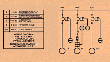
Electrical ladder drawings are still one of the common and reliable tools used to troubleshoot equipment when it fails.
Wire diagrams use wire color codes to identify the color of wire being used to connect different electrical components within the circuit. A well documented schematic outlines the functionality of an electric circuit and provides the basis for assembly and troubleshooting of a system. In electrical and electronics engineering, we use different types of drawings or diagrams to represent a certain electrical system or circuit. It shows how the electrical wires are interconnected and can also show where fixtures and components may be connected to the system. As you examine individual control circuits and the associated components that they operate, the overall diagram becomes easier to understand, as do the We'll go over all of the fundamental schematic symbols: Circuit or schematic diagrams consist of symbols representing physical components and lines representing wires or electrical conductors. Understanding electrical diagrams rv 7.11.19 5 quiz 3: Plus these two conductors will carry the current of all your electrical loads combined, so they are typically fairly beefy cables. Electrical ladder drawings are still one of the common and reliable tools used to troubleshoot equipment when it fails. It's not important to know these symbols by sight, you can reference the legend as you meet the various symbols along the circuits your reading. Here are some of the standard and basic symbols for various components for electrical schematics. We show our ac power source on the left with l1 and n coming out of it, our switch to the top, and our light to the left.