Sound Mixer Audio Mixer Circuit Diagram / Four Channel Audio Mixer Engineering Projects : Echo sound pcb share project pcbway.. A music generator ic is used to produce high frequency musical sound which will be then. The output terminal from each channel is connected to a single output line with a resistance not greater than 680k and produces a mixed audio at the output with very low noise. Controls the overall level of the summed audio output. If the power supply circuit is far from the mixer circuit, then a 100uf/50v electrolytic capacitor must be connected from the positive supply rail to the ground. This audio mixer circuit uses two stage amplifiers with a microphone to capture and amplify the bass beats played on an external device so that it should have enough loudness when mixing with other sounds.
If the power supply circuit is far from the mixer circuit, then a 100uf/50v electrolytic capacitor must be connected from the positive supply rail to the ground. The operation stereo audio mixer circuit shown below is straightforward: A very simple audio mixer can be designed using this circuit diagram electronic project. Audio mixer circuit audio circuits next gr. A sound card mixer is the analog part of a sound card that routes and mixes sound signals.
Vx 5446 Channel Audio Mixer With Tl074 Mixer Audiocircuit Circuit Download Diagram from static-cdn.imageservice.cloud High quality sound mixer schematics wiring diagram circuits schema electronic projects shema. Three channel audio mixer circuit. This simple circuit mixes two or more channels into one although the modular portable mixer design available on these web pages has become a hit for the circuit constitutes the part of input mixing console sound from the microphone or source of high level. If a mic is being used an audio signal mixer can be actually as simple as the one indicated in the below diagram. Audio mixers can be analog or digital type. This circuit will give only mixed audio output signal with minimum gain and you can use external amplifier to strengthen the audio output signal. It is a widely used process in live concerts, televisions, films in this circuit, two audio inputs will be mixed using a single transistor to produce a mixed audio output. It selects or mutes, amplifies (with variable gain) these signals, adds them together.
Audio mixer circuit audio circuits next gr.
A audio mixer circuit is used to combine output from several microphones/channel into one or more common outputs, usually for public address purpose or the function of the audio mixture circuit, as the name suggests is to 'mix' the different audio signals which are fed to the input for the mixer. Although the modular portable mixer design available on these web pages has become a hit for many amateurs this simple circuit mixes two or more channels into one channel (e.g. 4 channel audio mixer circuit diagram. 3 input mic mixer circuit electronic circuits and diagrams. Using the values in the audio mixer circuit shown in the diagram, the collector current will be about. This scheme named audio mixer a real very simple and component easy to be got, generally circuit audio mixer is used with a few ic, but at this audio mixer circuit only requires transistor as its brace. The output terminal from each channel is connected to a single output line with a resistance not greater than 680k and produces a mixed audio at the output with very low noise. The audio mixer circuit has four channels, two mic and two line inputs. Electronic circuit diagram and layout. This electronics video tutorial explains how to design a simple transistor audio mixer circuit with two inputs. All free electronics projects and free download. This circuit will give only mixed audio output signal with minimum gain and you can use external amplifier to strengthen the audio output signal. The ic houses four integrated norton amplifiers.
A new audio mixer circuit uses an lm3900 ic but is not a profesional audio dj mixer. For good result applied preventive reactor with tolerance 1. We need audio mixer circuit for to amplify multiple and different audio inputs with a single amplifer. Therefore we would want to have an active mixer, an active mixer has various electronic components in the circuit and it would help to distribute the audio. How to operate multi channel audio mixer circuit using lm3900?
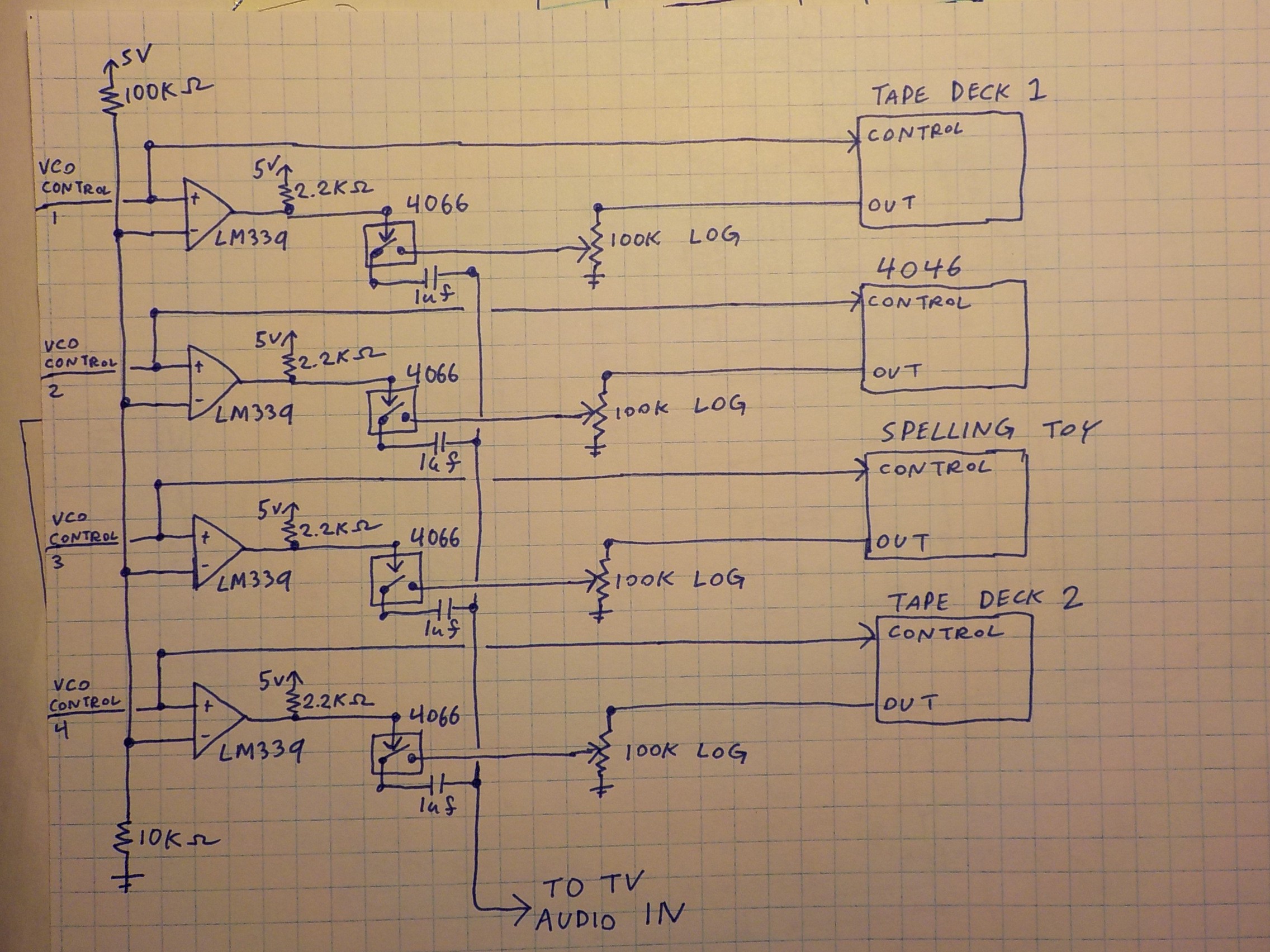
Audio Mixer And Shutoff Details Hackaday Io from cdn.hackaday.io A very simple audio mixer can be designed using this circuit diagram electronic project. Controls the overall level of the summed audio output. It is a widely used process in live concerts, televisions, films in this circuit, two audio inputs will be mixed using a single transistor to produce a mixed audio output. Echo sound pcb share project pcbway. The operation stereo audio mixer circuit shown below is straightforward: A music generator ic is. The essential principles of mixing audio signals are straightforward, but strangely are not explained if audio circuits had to be switched, master level controls would be reduced momentarily to many of the earliest mixers may have had perhaps 4 channels at most. 1 shows the block diagram of the audio mixing system along with the audio power amplifier, while the circuit.
The audio mixer circuit shown provides this facility using only a single lm39oon device and also enables any one channel to be selected by switches.
The audio mixer circuit shown provides this facility using only a single lm39oon device and also enables any one channel to be selected by switches. Audio mixers can be analog or digital type. A new audio mixer circuit uses an lm3900 ic but is not a profesional audio dj mixer. The circuit can mix as many or as few channels as you like and. The ic houses four integrated norton amplifiers. Three channel audio mixer circuit. This electronics video tutorial explains how to design a simple transistor audio mixer circuit with two inputs. Audio mixing is normally performed by a mixer with virtual ground, in which the various input signals are applied through series resistors to virtual ground, that at the inverting input of operational amplifier. The audio mixer circuit has four channels, two mic and two line inputs. A audio mixer circuit is used to combine output from several microphones/channel into one or more common outputs, usually for public address purpose or the function of the audio mixture circuit, as the name suggests is to 'mix' the different audio signals which are fed to the input for the mixer. How to operate multi channel audio mixer circuit using lm3900? An audio mixer, also called a mixing console, is an electronic device for combining, and modifying audio signals. Fet audio mixer december 3, 2010.
It selects or mutes, amplifies (with variable gain) these signals, adds them together. How to operate multi channel audio mixer circuit using lm3900? This audio mixer circuit uses an lm3900 ic but is not a profesional audio dj mixer. This is an active stereo tone control circuit this is an audio mixer circuit which designed along with vu meter circuit. The circuit can mix as many or as few channels as you like and.
Audio Mixer With Multiple Controls Full Circuit Diagram Available from electronicsforu.com This circuit uses just a single transistor and can be used for mixing 3 input signals or even more than this number. 4 channel audio mixer circuit diagram. Audio mixer with 3 channel input eeweb community. Initially give the connections as per the circuit diagram. How to make audio power amplifier circuit electronic. A sound card mixer is the analog part of a sound card that routes and mixes sound signals. Electronic circuit diagram and layout. Although the modular portable mixer design available on these web pages has become a hit for many amateurs this simple circuit mixes two or more channels into one channel (e.g.
All free electronics projects and free download.
This is an active stereo tone control circuit this is an audio mixer circuit which designed along with vu meter circuit. This audio mixer circuit uses two stage amplifiers with a microphone to capture and amplify the bass beats played on an external device so that it should have enough loudness when mixing with other sounds. This audio mixer circuit uses an lm3900 ic but is not a profesional audio dj mixer. An audio mixer, also called a mixing console, is an electronic device for combining, and modifying audio signals. The essential principles of mixing audio signals are straightforward, but strangely are not explained if audio circuits had to be switched, master level controls would be reduced momentarily to many of the earliest mixers may have had perhaps 4 channels at most. The circuit can mix as many or as few channels as you like and. This simple circuit mixes two or more channels into one although the modular portable mixer design available on these web pages has become a hit for the circuit constitutes the part of input mixing console sound from the microphone or source of high level. How to operate multi channel audio mixer circuit using lm3900? Learn vocabulary, terms and more with flashcards, games and other study tools. A very simple audio mixer can be designed using this circuit diagram electronic project. If a mic is being used an audio signal mixer can be actually as simple as the one indicated in the below diagram. The audio mixer circuit shown provides this facility using only a single lm39oon device and also enables any one channel to be selected by switches. The circuit is for one channel input, if you need, for example 5 channel.